
A CNC-machined component can fail even when its nominal dimensions appear correct. In automotive parts, textile and packaging machinery, custom automation equipment, and construction machinery, a small datum shift, excessive cutting force, burr, or dimensional change after finishing can prevent correct assembly. CNC Machining Services must therefore control not only dimensions, but also tool motion, workholding, datum relationships, surface condition, and inspection.
In this article, I examine how CNC Machining Services convert engineering drawings and CAD geometry into controlled material-removal operations, how machining errors develop, and which engineering parameters should be verified before a machined component is released.
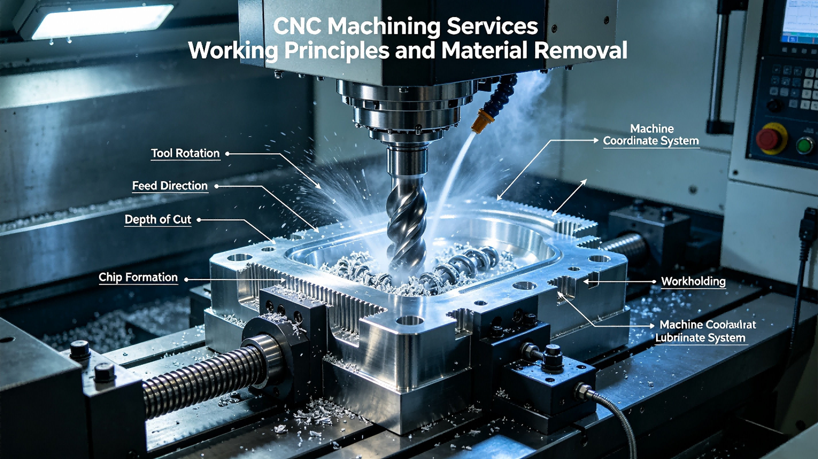
From an engineering perspective, CNC machining is a controlled material-removal process. The machine does not simply reproduce a CAD model. It converts geometric information into coordinated axis motion, spindle rotation, tool engagement, workholding conditions, and inspection requirements.
The process normally begins with engineering definition. The drawing or model establishes functional surfaces, dimensions, tolerances, holes, threads, radii, surface requirements, and datum relationships. These requirements determine how the component should be located and which features should be machined first.
The next step is process planning. A machinist or manufacturing engineer evaluates the stock material, feature accessibility, required tooling, workholding strategy, number of setups, machining sequence, and finishing requirements. The sequence matters because machining one feature can change the accessibility or reference condition for another.
During cutting, the rotating tool removes material from the workpiece. Cutting forces act on both the tool and component. If the workpiece is insufficiently supported, these forces can cause deflection. If the tool is too long or slender, tool deflection can contribute to dimensional error. If the cutting edge becomes worn, cutting forces and heat generation can change over the production run.
After roughing, intermediate operations may establish more accurate surfaces. Finishing passes then remove controlled amounts of material to establish functional dimensions and surface characteristics. For critical parts, inspection is used to determine whether the resulting geometry remains within the drawing requirements.
The engineering objective is therefore a chain rather than a single machining operation:
Define functional geometry.
Establish manufacturing datums.
Select a stable workholding method.
Develop an accessible tool path.
Control cutting forces and tool engagement.
Finish critical surfaces.
Inspect dimensions and geometric relationships.
Verify that post-processing has not changed functional interfaces.
When we examine a machining failure, I normally trace this chain backward rather than assuming that the final dimensional error originated during the final cutting pass.
The supplied technical requirement states that the product should comply with applicable European and American requirements. Because no certificate number, issuing body, or named standard has been supplied, no specific certification or standard number is asserted here. The applicable standard and certificate status should be verified against the current manufacturer documentation before inclusion in an engineering specification.
Under mechanical loading, machining accuracy becomes a functional issue. A hole can have the correct diameter but still be incorrectly positioned. Two shafts can have acceptable individual diameters but fail to assemble if their positional relationship is incorrect. A flat mounting surface can meet a nominal size while failing a required flatness relationship.
This distinction between size and geometry is fundamental to CNC engineering.
A CNC machining system consists of several interacting engineering elements. Treating the machine tool as the only important component overlooks the contribution of tooling, workholding, programming, material condition, and inspection.
| Component | MaterialSpec | Function | Failure Risk if Compromised |
|---|---|---|---|
| Machine Tool | Verify current machine configuration and capability | Provides controlled axis movement and spindle rotation | Positioning error, vibration, thermal drift, or insufficient rigidity can affect geometry |
| Cutting Tool | Verify tool grade, geometry, diameter, and coating for the work material | Removes material while establishing feature geometry | Wear, deflection, chipping, or runout can cause dimensional and surface errors |
| Workholding System | Verify fixture, vise, chuck, soft jaw, or dedicated locating method | Locates and constrains the workpiece | Workpiece movement or distortion can shift the machining datum |
| CNC Program | Verify post-processed program against the approved geometry | Controls tool motion, cutting sequence, and machining coordinates | Incorrect coordinates or sequence can create wrong features or collisions |
| Workpiece Material | Verify material designation and condition from current material documentation | Provides the substrate from which the component is produced | Residual stress, hardness variation, or unsuitable condition can affect stability |
| Inspection Equipment | Verify current calibration and measurement capability | Confirms dimensional and geometric conformity | Measurement uncertainty or incorrect datum interpretation can produce false acceptance |
pemVerify all parameters against current test reports and applicable standards before use in specifications.emp
The workholding system deserves particular attention. A fixture does not merely hold the component against movement. It establishes how the component relates to the machine coordinate system. If the fixture locates the workpiece from a different physical surface than the engineering drawing assumes, dimensional relationships can be transferred incorrectly between operations.
Tool selection is equally important. A tool with excessive stick-out can deflect under cutting load. A tool that cannot physically reach a deep pocket may force a different machining strategy. A small internal corner may require a smaller cutter, which can increase machining time and reduce cutting stability.
Inspection equipment closes the engineering loop. Measurement should reproduce the functional datum logic of the drawing. Measuring a dimension without correctly establishing the relevant reference system can generate a number that looks precise but does not represent the actual functional relationship.
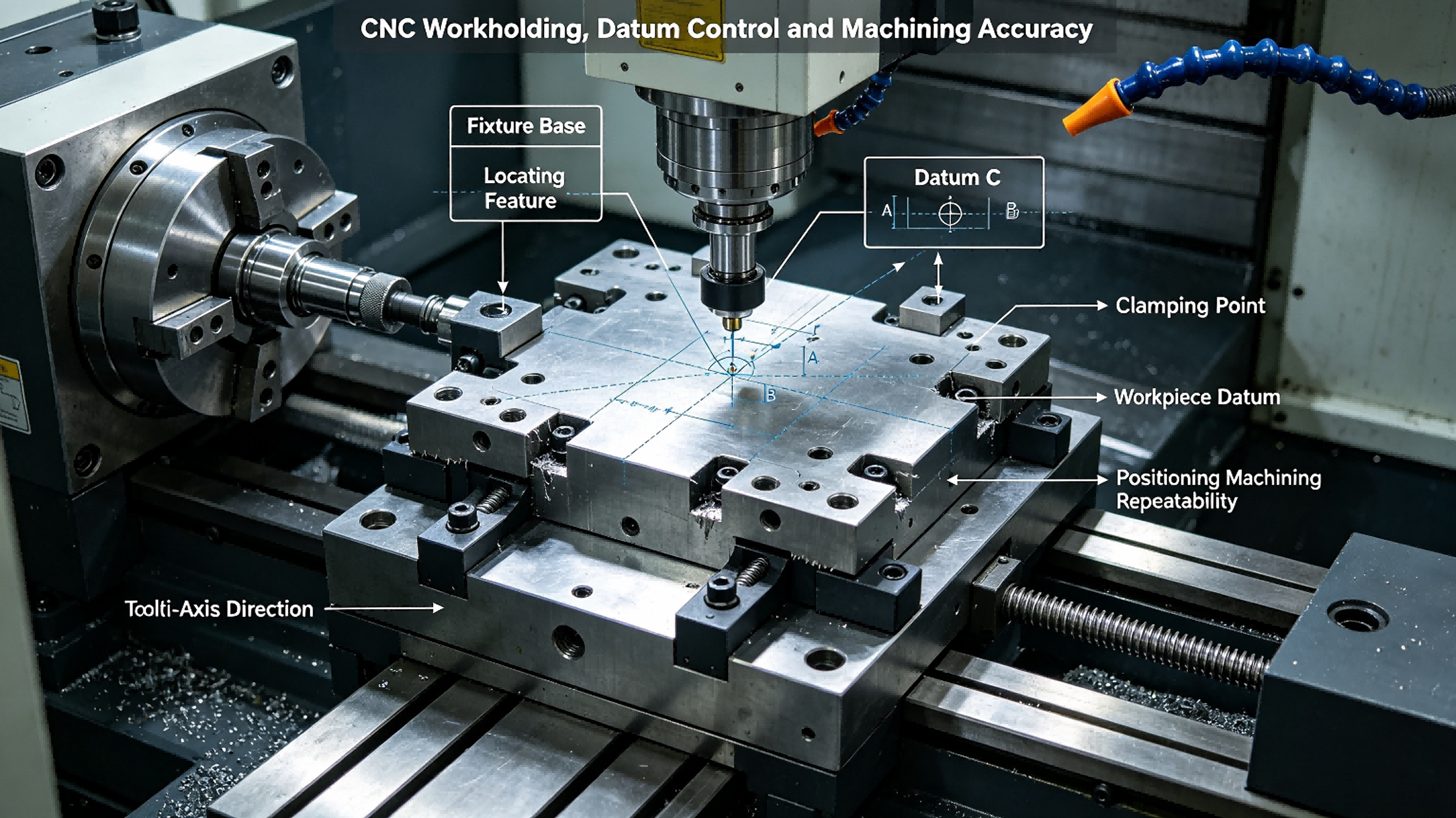
For CNC-machined components, performance parameters should be defined according to the actual function of the component rather than by applying one generic precision value to every feature.
| Parameter | Standard | Test Method | Acceptable Range | Implication if Out of Range |
|---|---|---|---|---|
| Linear Dimension | Project drawing and applicable verified requirement | Calibrated dimensional measurement | As specified on the approved drawing | Can interfere with assembly or functional clearance |
| Position | Project drawing and applicable verified requirement | Coordinate measurement or appropriate calibrated method | As specified by the geometric requirement | Can cause hole-pattern or assembly misalignment |
| Flatness | Project drawing and applicable verified requirement | Appropriate calibrated surface measurement method | As specified on the drawing | Can create uneven mounting or sealing interfaces |
| Surface Roughness | Project drawing and applicable verified requirement | Suitable calibrated surface roughness measurement | As specified on the drawing | Can influence friction, sealing, wear, or appearance |
| Thread Geometry | Project drawing and applicable verified requirement | Appropriate thread gauges or dimensional inspection | As specified by the approved drawing | Can prevent mating or reduce effective thread engagement |
pemVerify all parameters against current test reports and applicable standards before use in specifications.emp
When no verified numerical value is available, I would not replace the missing value with a typical CNC tolerance. The correct engineering procedure is to return to the drawing, customer specification, or current inspection report.
This is particularly important for automotive and industrial machinery components. A tolerance that is acceptable for a non-functional external surface may be unsuitable for a bearing seat, locating hole, sealing interface, or precision shaft relationship.
Geometric tolerances require the same discipline. A component can satisfy its basic size requirement while failing flatness, perpendicularity, parallelism, position, or runout. The measurement method must therefore reflect the characteristic being controlled.
For critical interfaces, inspection should also consider the datum system. If the drawing establishes a primary, secondary, and tertiary datum, the inspection method should reproduce that reference sequence where applicable.
The primary protection mechanism in CNC machining is controlled removal of material while maintaining the relationship between the workpiece, cutting tool, machine coordinate system, and engineering datums.
Post-processing creates a second layer of dimensional control. Anodizing, bead blasting, powder coating, polishing, plating, or other finishing processes should not be treated as purely cosmetic operations when they affect functional interfaces. The engineering question is not simply whether a surface looks uniform. It is whether the final processed surface remains within the dimensional and assembly requirements.
For a threaded hole, coating deposited on the internal surface can reduce effective clearance. For a shaft, an applied surface layer can increase the finished diameter. For a mating bore, coating can reduce available clearance. For a datum surface, uncontrolled finishing can change the surface condition used for assembly or inspection.
The appropriate process therefore begins before machining. The drawing should identify cosmetic surfaces separately from functional surfaces where the application requires that distinction. Functional bores, threads, bearing interfaces, sealing areas, locating faces, and mating surfaces may require masking or a defined finishing condition.
The dimensional chain can be represented as:
Nominal CAD or drawing dimension.
Machining allowance or process stock.
Pre-finish dimensional verification.
Specified finishing process.
Surface-layer or material-removal effect.
Masking of designated functional areas where required.
Final dimensional verification.
Assembly-interface verification.
This chain becomes particularly important when tight tolerances are combined with surface treatment. The available dimensional envelope is not unlimited. If a feature is already machined close to its functional boundary, adding a finishing process without accounting for its dimensional effect can move the feature outside its allowable condition.
Small-batch CNC production introduces another engineering relationship: tolerance, tooling, machining path, inspection effort, and process time are coupled. A tighter tolerance can require additional finishing passes, more stable workholding, better control of tool wear, additional inspection, or a more controlled machining sequence. The effect is not simply a change in the number printed on a drawing.
For example, a narrow internal slot may require a smaller cutter. The smaller cutter may have lower stiffness than a larger tool. Lower stiffness increases sensitivity to cutting force and tool deflection. If the slot also has a deep aspect ratio, tool accessibility and chip evacuation become additional constraints. The resulting process may require a different tool path and more inspection than a shallow, open feature.
Thin-wall components introduce a related problem. During machining, cutting forces are transferred through the remaining wall into the workholding system. If the wall is thin enough that its stiffness is low, the measured geometry during clamping can differ from the geometry after release. The component may spring back when the external constraint is removed.
Clamping force can also contribute to this effect. Excessive clamping pressure can distort a compliant component during machining. If the machining process removes material while the component is distorted, the resulting free-state geometry may no longer match the clamped-state geometry.
Residual stress can produce another dimensional change. Material that contains internal stress may deform after significant material removal. Roughing can expose a new stress distribution, while subsequent finishing removes additional material and changes the balance again. A stable process therefore considers the sequence of roughing, intermediate operations, finishing, and final inspection.
Deep-hole machining has its own failure mechanisms. As hole depth increases relative to diameter, tool guidance, chip evacuation, coolant delivery, and tool deflection become more important. A deep hole can exhibit diameter variation or axis deviation even when the entry location is correct. The engineering response is to select a drilling strategy appropriate to the geometry and verify the resulting hole rather than assuming that a successful entry operation guarantees the complete hole is correct.
Threaded features require similar attention. Tapping and Thread Milling generate the same nominal thread function through different cutting mechanisms. Thread milling can offer process flexibility for certain applications and materials, while tapping can be efficient when the geometry and process conditions are appropriate. Blind holes additionally require consideration of bottom clearance and effective thread depth.
Tool wear creates a time-dependent mechanism. As a cutting edge wears, cutting forces can increase and the relationship between commanded tool movement and actual material removal can change. Surface roughness can also change. For small-batch production, this means the first part and later parts should not automatically be assumed to have identical process behavior.
Tool condition monitoring, offset compensation, in-process inspection, and defined inspection intervals can reduce this risk when they are appropriate to the component.
GD&T provides another protection mechanism because it controls relationships rather than isolated dimensions. Position controls where a feature lies relative to a datum reference system. Parallelism controls orientation relative to a reference. Flatness controls a surface independently of a datum. Runout controls the behavior of a surface relative to a specified axis or datum reference.
This explains why a part can pass dimensional inspection yet fail assembly. Consider two holes that both have acceptable diameters. If their positional relationship is outside the functional requirement, the mating component may not enter even though neither hole is individually oversized or undersized.
Datum selection is therefore linked directly to machining strategy. If Datum A is the functional mounting face, it may also become an important manufacturing reference. Datum B and Datum C can establish orientation and lateral location. When a component requires several setups, transferring these relationships between setups becomes a key source of cumulative error.
Using a machining strategy that completes related features in fewer setups can reduce opportunities for datum shift. Multi-axis machining can also improve tool accessibility and reduce the need to reposition certain complex components. However, 3+2 positioning and simultaneous five-axis cutting are different process concepts and should not be treated as interchangeable labels.
Tool accessibility is another fundamental engineering constraint. A cutter must physically reach the feature with adequate clearance. Deep pockets, narrow slots, internal corners, undercuts, and hidden surfaces can restrict the available tool diameter and length. A design with a larger internal radius may permit a stiffer cutter, while excessive pocket depth can require a longer and more flexible tool.
These geometric relationships also influence automated CNC quotation and process planning. A manufacturing system can evaluate material volume, feature depth, number of setups, tool accessibility, thread count, tolerance requirements, and surface requirements when estimating process complexity. The engineering value of such analysis is not simply generating a price; it is identifying manufacturability constraints before machining begins.
For high-mix, low-volume production, CNC can also be evaluated alongside additive manufacturing and other processes. Metal load-bearing components with critical interfaces generally require different engineering considerations from polymer housings or geometrically complex non-load-bearing components. The appropriate process should be selected from the functional requirements, dimensional stability, material behavior, surface requirements, and downstream assembly process rather than from geometry alone.
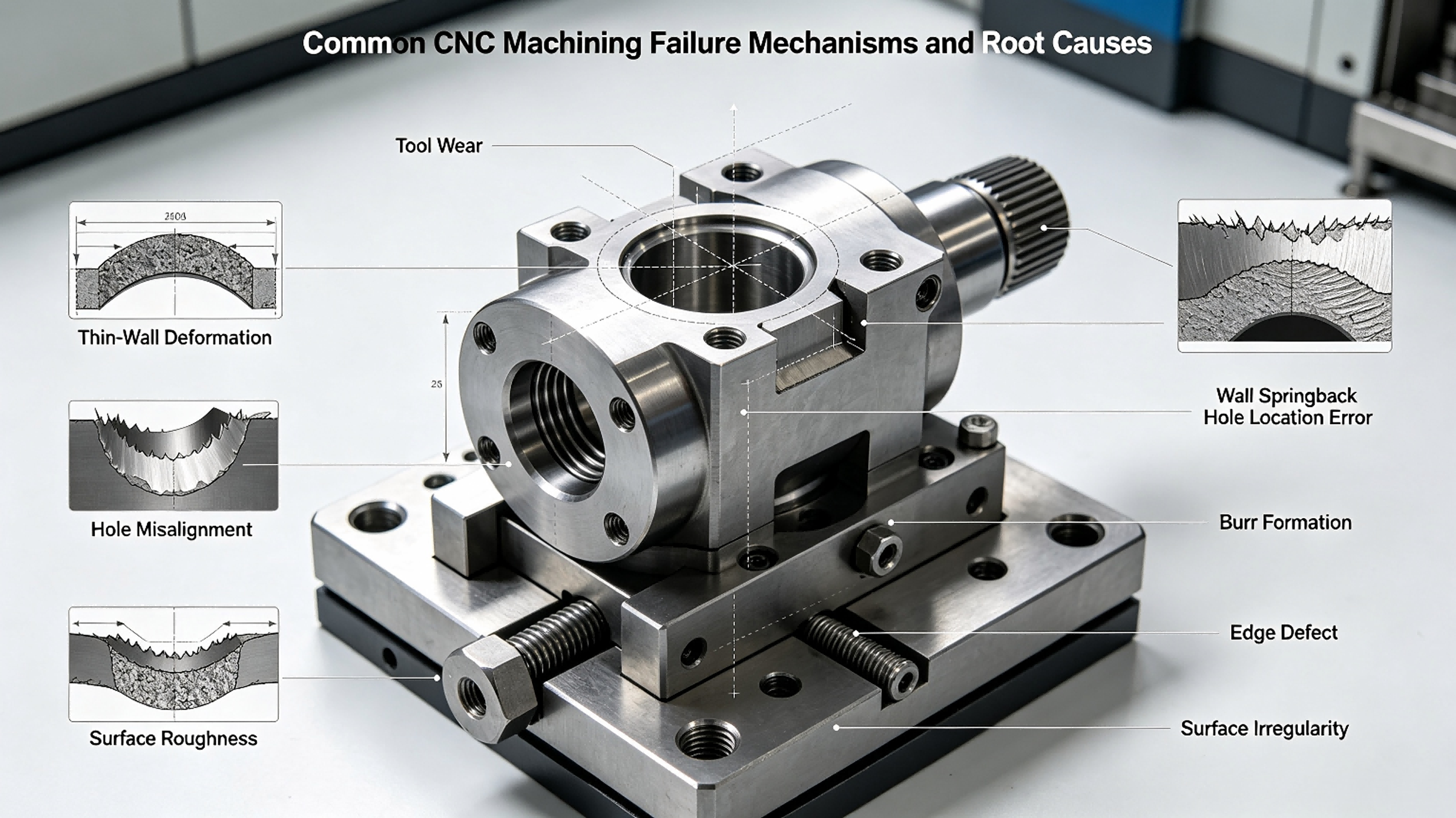
| Failure | Root Cause | Engineering Consequence | Prevention |
|---|---|---|---|
| Hole pattern misalignment | Datum shift between machining setups changes the positional relationship between hole groups | Mating component cannot align with the complete hole pattern | Control datum transfer and verify positional relationships using an appropriate inspection method |
| Thin-wall dimensional change after release | Clamping force and cutting force deform the wall during machining | Free-state geometry differs from the measured clamped condition | Control workholding force, machining sequence, remaining wall stiffness, and final free-state inspection |
| Finished bore outside functional size | Surface treatment changes the bore dimension without adequate finishing allowance or masking | Mating shaft or component clearance becomes unacceptable | Define finishing allowance and functional masking requirements before final machining |
| Surface roughness deterioration during a batch | Progressive cutting-edge wear changes cutting forces and tool-workpiece interaction | Later parts can show a different surface condition from early parts | Define tool-life monitoring and inspection intervals appropriate to the component |
| Thread assembly failure | Insufficient effective thread depth, burr formation, dimensional error, or finishing material on the thread | Fastener cannot fully engage or reaches insufficient engagement | Control thread geometry, deburring, finishing, and thread verification |
| Part warpage after machining | Material residual stress is released as machining removes asymmetric material volumes | Component moves outside the required free-state geometry | Control material condition and machining sequence, then inspect after the component is released from workholding |
pemVerify all parameters against current test reports and applicable standards before use in specifications.emp
When we examine failure reports, the useful question is rarely “Was the CNC machine accurate?” A better question is which mechanism introduced the error. A machine can be capable of producing a feature accurately while the selected fixture, datum transfer, tool condition, or inspection method introduces an unrelated error.
Root-cause analysis should therefore follow the physical mechanism from drawing requirement to final condition.
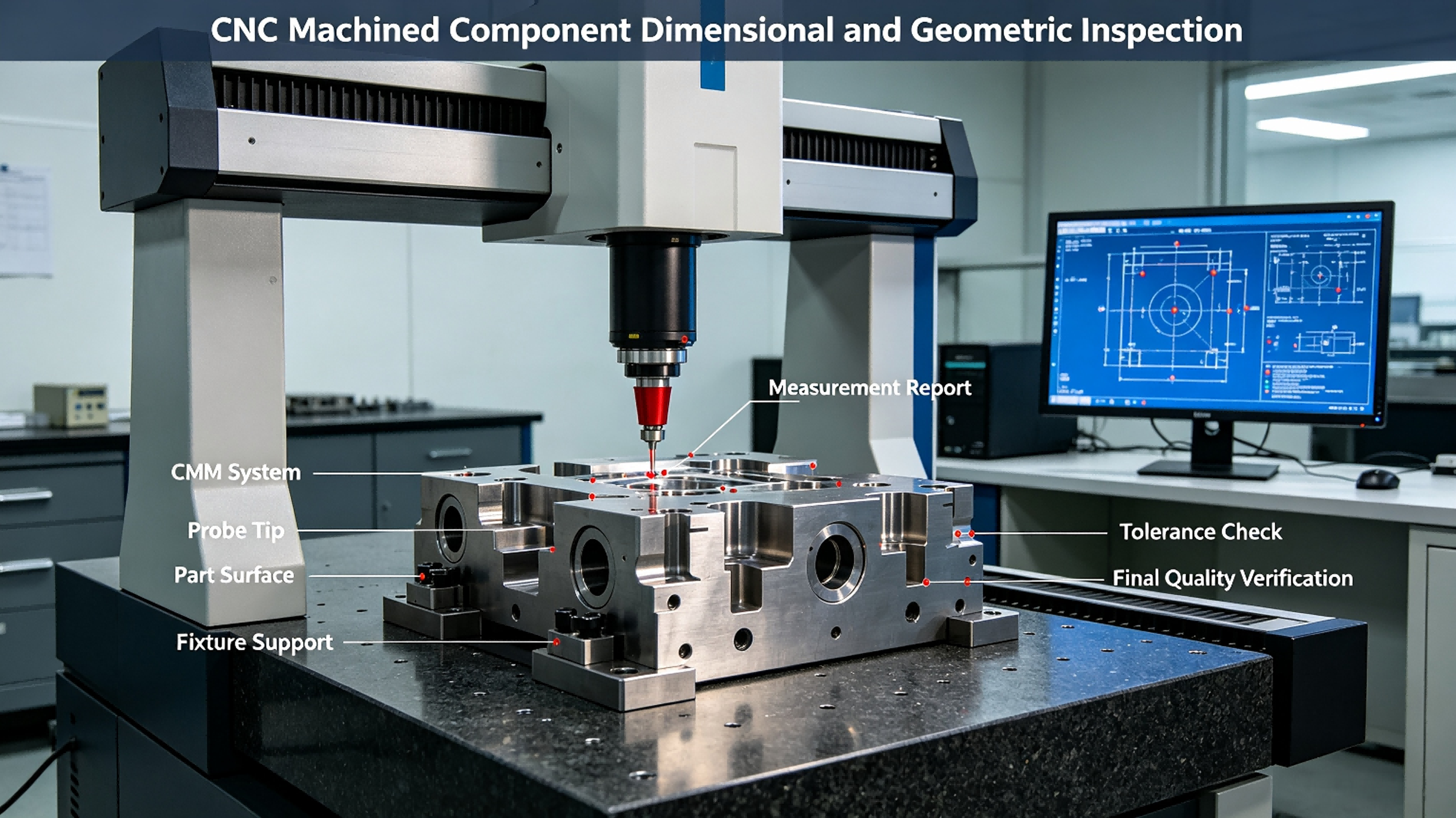
The following checklist can be used when preparing a CNC machining specification for automotive, textile and packaging machinery, custom automation equipment, or construction machinery components.
Structural requirements: Define load-bearing surfaces, mounting interfaces, critical holes, shafts, slots, pockets, and other functional features.
Dimensional requirements: Identify all critical dimensions and distinguish general dimensions from function-critical dimensions.
Geometric requirements: Define applicable flatness, parallelism, perpendicularity, position, concentricity, and runout requirements according to the approved drawing.
Datum requirements: Identify primary, secondary, and tertiary datums where applicable and ensure machining and inspection reference the intended functional geometry.
Material requirements: Specify the required material designation and condition from verified engineering documentation.
Tool accessibility: Check internal corners, deep pockets, narrow slots, undercuts, hole depth, and cutter clearance before machining.
Workholding: Establish how the component will be located without creating unacceptable deformation.
Surface requirements: Identify functional surfaces separately from cosmetic surfaces and specify surface condition where function requires it.
Post-processing: Define the required finishing process and identify surfaces, holes, threads, shafts, and mating interfaces that require dimensional protection or masking.
Thread requirements: Specify thread form, size, depth, effective engagement, blind-hole conditions, and applicable inspection method according to the approved drawing.
Inspection: Identify critical dimensions and determine whether conventional calibrated measurement, CMM, gauges, or another method is appropriate.
First Article Inspection: Establish the dimensional and geometric verification required before proceeding from prototype validation into low-volume production.
Process consistency: Define inspection intervals and tool-condition controls where tool wear could affect dimensional stability.
Final verification: Confirm the component in its relevant free-state condition and after applicable post-processing.
Standards and certifications: List only verified standards and certifications applicable to the actual project documentation.
Share your project parameters for a technical review.
Dongguan city Jifan Precision Machinery Co., Ltd is described for this project as a source manufacturing factory with automated production lines and capabilities for R&D prototyping and customized machining; these capabilities should be verified against current production and quality documentation when used in a technical specification.
When evaluating any CNC manufacturer, I would examine whether engineering staff can translate drawings into stable machining processes, establish suitable datums, control workholding deformation, select accessible tooling, manage tool wear, inspect geometric tolerances, and maintain process consistency from first article through low-volume production.
A function-critical dimension should not be assigned an invented tolerance; it should be clarified against the approved engineering drawing or applicable project requirement.
Applying a generic machining tolerance can unintentionally change an assembly clearance or locating relationship. The final requirement should be verified before the dimension is released for manufacturing.
The hole diameter can be correct while the hole position, orientation, or relationship to the relevant datum is outside the functional requirement.
This is why geometric control can be as important as dimensional control. An appropriate inspection method should reproduce the functional datum structure when verifying the hole relationship.
A post-processing operation can change the dimensional condition of a surface by adding material, removing material, or altering the surface texture.
Internal threads, bores, shafts, bearing interfaces, sealing surfaces, and locating faces should therefore be reviewed before finishing. Any required allowance or masking condition should be established before final machining.
The component may have been elastically deformed by workholding and cutting forces during machining.
Once the clamping force is released, the stored elastic deformation can recover. Residual stress released during material removal can create an additional dimensional change, so final inspection should consider the component's free-state condition.
Reducing setups can be beneficial when multiple features must maintain a precise positional relationship and re-establishing the datum would introduce unnecessary variation.
The appropriate strategy depends on feature accessibility, workholding, machine capability, part geometry, and required geometric relationships. 3+2 positioning and simultaneous multi-axis machining should be evaluated according to the actual feature geometry rather than treated as equivalent processes.
Ce site Web utilise des cookies pour vous garantir la meilleure expérience sur notre site Web.

 English
 Español
 Portugues
 Pусский
 Deutsch
 日本語
日本語 한국어
한국어 العربية
 Italiano
 Nederlands
 Svenska
 Polski
 ไทย
ไทย Türk dili
 Indonesia
 Tiếng Việt
 čeština
 Română
 Suomalainen


Commentaire
(0)